Meter Loop Wiring Diagram
Notice that we are going to be metering a single phase three wire service. Before beginning this project be certain the electricity has been disconnected at the meter loop or the pole.
 Wiring A Meter 6s Wiring Diagram 500
 These set of drawings are more detailed than process and instrument diagrams pids.
Meter loop wiring diagram. Failure to follow these instructions could cause an explosion resulting in death or serious injury. Loop diagrams are the most detailed form of diagrams for a control system and thus it must contain all details omitted by pfds and pids alike. Make note that this is the same type of service that you find on most homes.
We have two phase wires and a neutral. Watch this recorded webinar designed as an introductory class for those who have to deal with two wire loop powered meters and other devices. Form 4s meter wiring diagram.
Show 4 loops series field show 3 loops commutating or compensating field show 2 loops. Meter enclosure a wood or metal cabinet or metal socket installed indoors or outdoors in which the companys metering equipment is located. Meter a device for measuring the electric power and energy supplied to a customer.
Hi guys how are you today. Revised ls 805 minimum specifications for pole mounted permanent overhead meter loops. The electric meter is usually a clear glass encased metering device resembling an over sized mason jar.
Inside the glass houses the measuring devices that include dials and wheels on the older model meters. A new project requires a licensed electrician to pass city inspections. The only difference is that it is larger.
The electric meter exists so that the power company can monitor current usage and bill you accordingly. For the form 4s meter wiring diagram lets start at the bottom. However knowing how to wire a main breaker box can help a homeowner determine issues that may be stemming from the electrical wiring.
Any unsafe wiring found will not be connected until it has been corrected by the customer. Meter sockets a meter socket is the base portion of a socket type meter. If installed in explosive atmospheres hazardous areas classified areas or an ex.
Meter shunt fuse thermocouple. Hopefully the pictures above wiring diagram can be useful. Instrument loop diagrams are also called instrument loop drawings or loop sheets.
Wiring diagram since wiring connections and terminal markings are shown this type of diagram is helpful when wiring the. Gain a strong understanding of the key criteria for using and specifying a loop powered device and know when a loop powered device is appropriate for your application. G l1 l2.
Co op personnel are not allowed to work on the customers meter pole or wiring. See drawing on the front of this sheet for an example of a typical meter pole.
 Solved 10 A Circalar Loop Of Wire Of Resistance 02 Ohm En
  Electrical Infographic Home Electrical Wiring Electrical High Speed Closed Loop Servo Tensioner With Maximum Wire Feeding Speed Of 18 Meters Second
 /Electric-Meter-Wired-300-56a27f885f9b58b7d0cb5592.jpg) How To Wire An Electric Meter
How To Wire An Electric Meter  W1tr 80 Meter Vertical Loop
 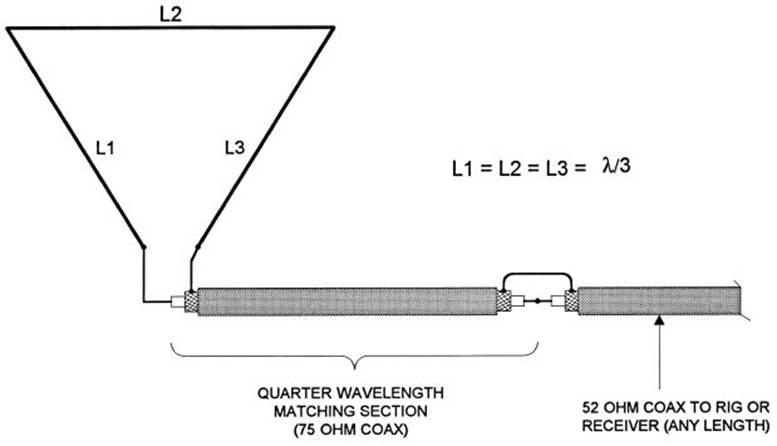 Top Band Hams 22 Different Wire Antennas For The 160 Meter
  Schematic Of The Two Phase Loop Of Testing Esp At Tulsa
  Pump Flow Meter And Reservoir Make The Loop For
 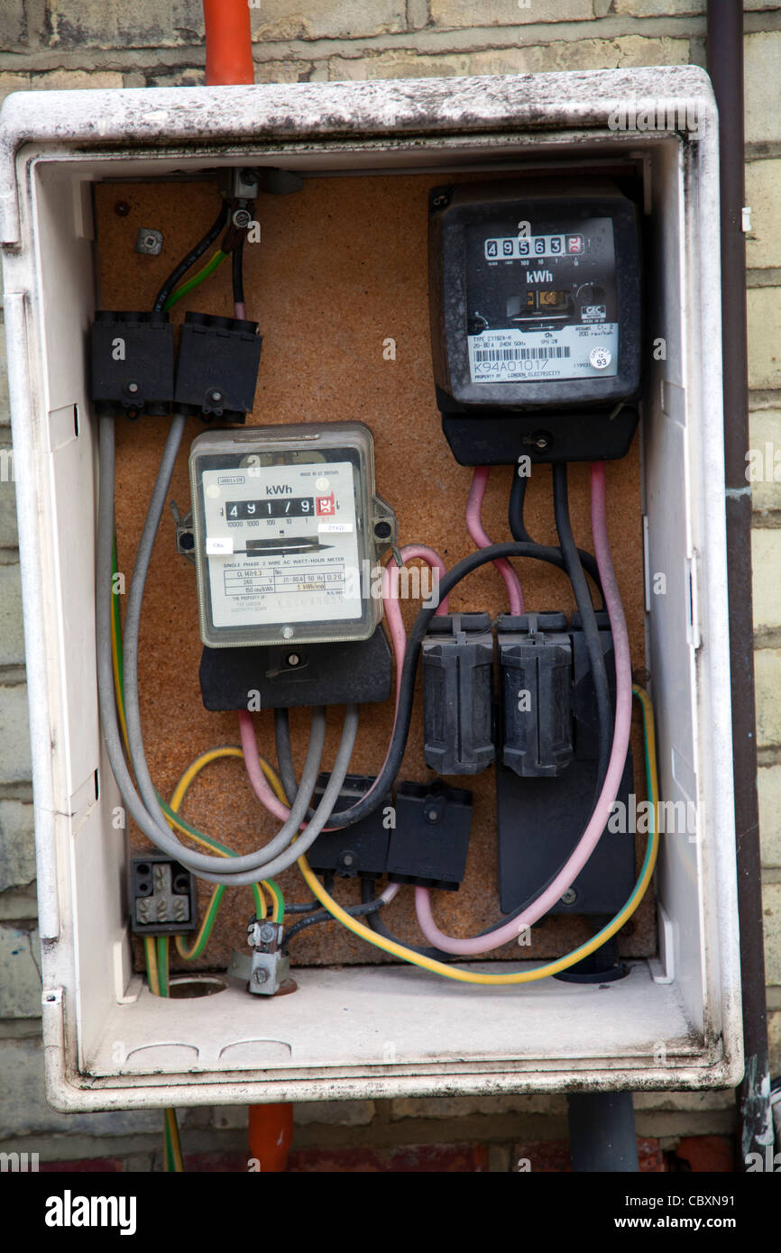 Meter Box Wiring Wiring Diagram Dash
Posting Komentar untuk "Meter Loop Wiring Diagram"